
Objective
To design and validate a multi-vendor network discovery environment where both Cisco Discovery Protocol (CDP) and Link Layer Discovery Protocol (LLDP) coexist without interference.
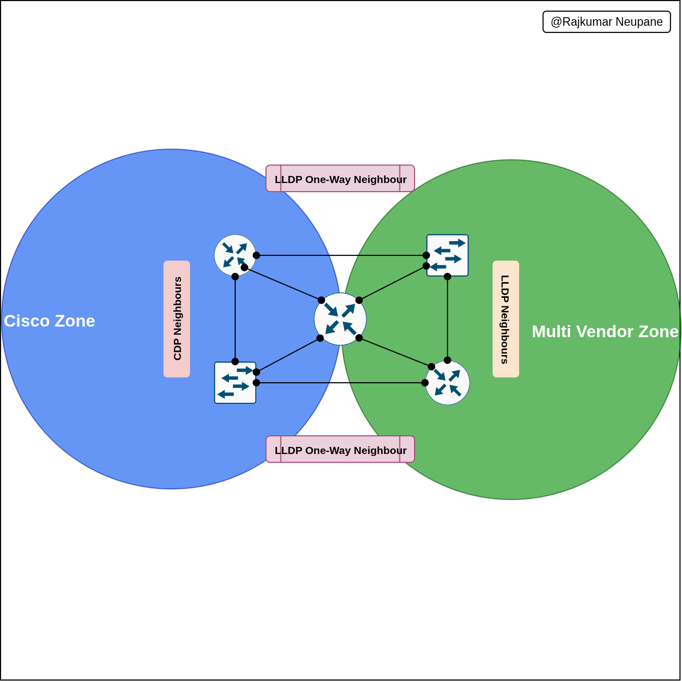
The goal is to segregate Cisco-to-Cisco communication zones from multi-vendor interoperability zones — ensuring that each protocol operates only where it’s most effective.
Scenario Overviewd
In a mixed enterprise environment, not all devices support CDP.
Routers and switches that connect to Cisco equipment use CDP for detailed neighbor discovery, while ports facing third-party or open-standard devices use LLDP.
This selective configuration demonstrates protocol separation, control, and vendor interoperability testing.
Implementation Summary
| Device | Cisco Zones (CDP) | Multi-Vendor Zones (LLDP) | Protocol Behavior | Notes / Purpose |
|---|---|---|---|---|
| Router1 | e0/1, e0/2 | e0/0, e0/3 | CDP enabled on Cisco zones; LLDP transmit-only on multi-vendor links | Prevents overlap, shares link info with non-Cisco devices |
| Router2 | e0/0, e0/2 | e0/1, e0/3 | CDP and LLDP separated by interface | Clean protocol boundaries, avoids duplicate discovery |
| Router3 | —- | All Ethernet ports (LLDP active) | LLDP transmit-only on e0/2; CDP active only on select Cisco links | Ensures full LLDP visibility, keeps backward Cisco compatibility |
| Switch1 | e0/0, e0/1 | e0/2 (receive-only) | CDP for Cisco links; LLDP limited to receiving on multi-vendor port | Acts as bridge between Cisco and multi-vendor zones |
| Switch2 | — | e0/0–e0/3 (except e0/3 receive-only) | LLDP transmit/receive on all, CDP disabled | Pure LLDP environment for interoperability testing |
Result
This topology cleanly divides discovery domains:
-
CDP zones: internal Cisco-to-Cisco connectivity
-
LLDP zones: external or third-party interoperability points
The result is a hybrid, controlled discovery environment that demonstrates professional-grade network segmentation and multi-vendor awareness — a critical skill in modern enterprise networks where Cisco gear coexists with other vendors.
Command On Each Device
Router1
Goal:
CDP on e0/1 & e0/2 (Cisco zone)
LLDP on e0/0 (Tx/Rx) and e0/3 (Tx only)
conf t
! --- Enable CDP globally
cdp run
! --- Enable LLDP globally
lldp run

! --- CDP-enabled interfaces
int e0/1
 cdp enable
 no lldp transmit
 no lldp receive
exit

int e0/2
 cdp enable
 no lldp transmit
 no lldp receive
exit

! --- Unused Port
int e0/0
 no cdp enable
 no lldp transmit
 no lldp receive
exit
! --- LLDP-enabled interface
int e0/3
 no cdp enable
 lldp transmit
 no lldp receive
exit
Router2
Goal:
CDP on e0/0 & e0/2
LLDP on e0/1 & e0/3
conf t
cdp run
lldp run

! --- CDP zone
int e0/0
 cdp enable
 no lldp transmit
 no lldp receive
exit

int e0/2
 cdp enable
 no lldp transmit
 no lldp receive
exit

! --- LLDP zone
int e0/1
 no cdp enable
 lldp transmit
 lldp receive
exit

int e0/3
 no cdp enable
 lldp transmit
 lldp receive
exit
Router3
Goal:
CDP disabled Globally
LLDP on all Ethernet ports (Tx/Rx), except e0/2 Tx only
conf t
no cdp run
lldp run

! --- LLDP on all Ethernet
int e0/0
 lldp transmit
 lldp receive
exit
! --- UNused Port
int e0/1
 no lldp transmit
 no lldp receive
exit

int e0/2
 lldp transmit
 no lldp receive
exit

int e0/3
 lldp transmit
 lldp receive
exit

! --- CDP kept for Serial interfaces in CML entering Serial interface of this device is not permit
int range s1/0 - 1/3
 no lldp transmit
 no lldp receive
exit

end
wr
Switch1
Goal:
CDP on e0/0 & e0/1
LLDP receive-only on e0/2
conf t
cdp run
lldp run

! --- Cisco zone (CDP)
int e0/0
 cdp enable
 no lldp transmit
 no lldp receive
exit

int e0/1
 cdp enable
 no lldp transmit
 no lldp receive
exit

! --- Multi-vendor receive-only LLDP
int e0/2
 no cdp enable
 no lldp transmit
 lldp receive
exit

! --- Disable LLDP entirely on e0/3
int e0/3
 no cdp enable
 no lldp transmit
 no lldp receive
exit

end
wr
Switch2
Goal:
CDP disabled Globally
LLDP on all interfaces (Tx/Rx), except e0/3 Rx-only
conf t
no cdp run
lldp run

! --- LLDP full Tx/Rx
int range e0/0 - 2
 no cdp enable
 lldp transmit
 lldp receive
exit

! --- LLDP Rx-only
int e0/3
 no cdp enable
 no lldp transmit
 lldp receive
exit

end
Summary Table
| Device | CDP Interfaces | LLDP Interfaces (Tx/Rx) | Special Cases |
|---|---|---|---|
| Router1 | e0/1, e0/2 | e0/0 (Tx/Rx), e0/3 (Tx only) | – |
| Router2 | e0/0, e0/2 | e0/1, e0/3 | – |
| Router3 | e0/1 + Serial ports | e0/0, e0/1, e0/3 | e0/2 Tx only |
| Switch1 | e0/0, e0/1 | e0/2 Rx only | – |
| Switch2 | None | e0/0–e0/2 (Tx/Rx) | e0/3 Rx only |
Download YAML File For CMLFile